«- back to print version table of contents
Tight Low-level Reflectivity Gradient
Detection
A Tight Low-level Reflectivity Gradient refers to the quick gradation from low reflectivities to high reflectivities (storm core) over a few kilometres in the vicinity of the Weak Echo Region (WER) or Bounded Weak Echo Region (BWER), the location of the updraft in a strong thunderstorm.
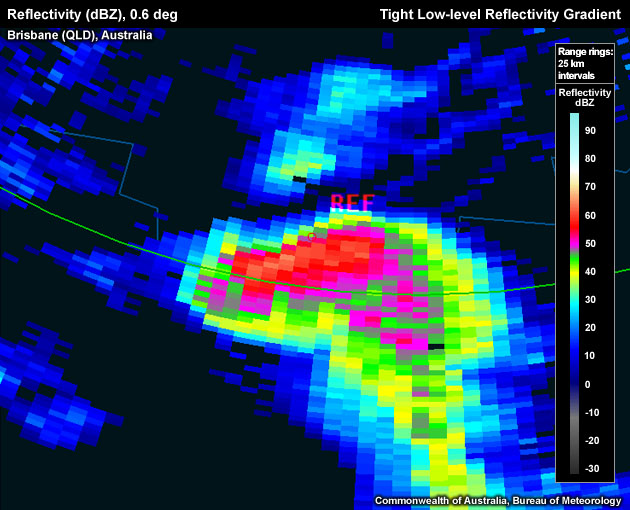
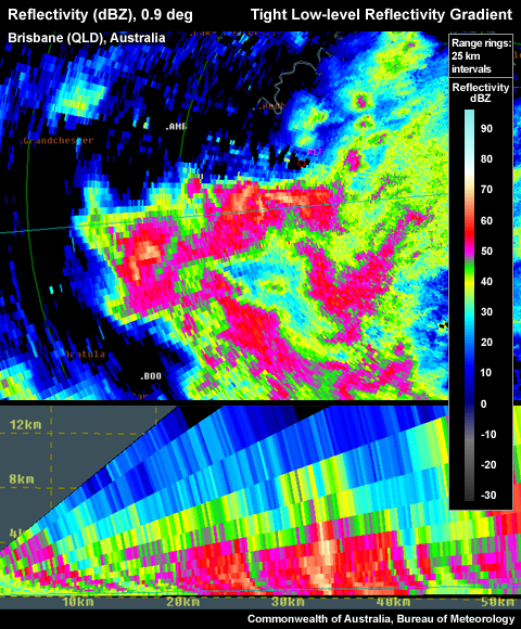
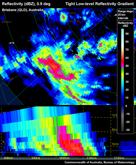
Tight low-level reflectivity gradient on the northern flank of the storm. Note the reference point (storm top) sitting right above the low level gradient.
To determine if the signature you are seeing is a Tight Low-level Reflectivity Gradient use the following technique:
Reflectivity: PPI/Plan View
Determining the inflow/updraft location:
- Step up in elevation scans until you run out of >50 dBZ echoes.
- Step down one elevation scan.
- Centre cursor on the upshear side of >50 dBZ core (this is to account for storm movement during the time that elapsed between the lowest tilt radar scan and the storm top scan).
- Set a reference point.

The reference point (storm top) is located well outside the low–level core.
- Step down to the lowest elevation scan.
- Is there a tight reflectivity gradient on the edge of the low-level core in the vicinity of the reference point? If yes, a Tight Low-level Reflectivity Gradient is present.
Reflectivity: RHI/Cross-Section
- Follow steps 1–5 from Reflectivity: PPI/Plan View (see above)
- Choose a cross section through the reflectivity core at the lowest tilt and the reference point you set in the upper levels, representing the approximate storm top. Note: usually you will need to use an arbitrary cross section rather than a radial cross section linked to the radar origin.
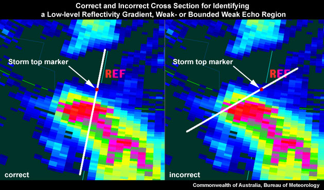
The image on the left is a correct cross section for identifying a tight low–level reflectivity gradient, as the most direct path from the low-level reflectivity core to the location of the upper level reflectivity core is used. The image on the right shows an inappropriate cross section, as the most direct path is not used.
- Is there a tight reflectivity gradient on the edge of the lower core in the vicinity of the reference point? If yes, a Tight Low-level Reflectivity Gradient is present.
Proper location of Tight Low-level Gradient on northern side in PPI.
Potential Difficulties in Detection
Radar Sampling – If the thunderstorm is too far away from the radar, the beam may overshoot the signature, and the broadening beam at a distance will also struggle to indicate the sharpness of the low-level reflectivity gradient.
Examples of Tight Low-level Refelctivity Gradients
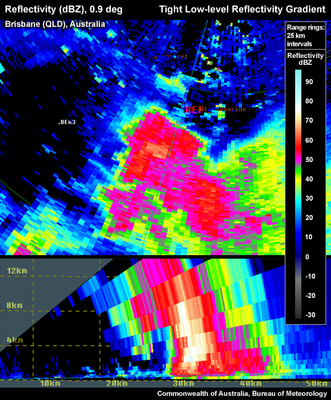
Tight low-level reflectivity gradient on the northern flank of the storm. Note the reference point (storm top) is located right above the low level gradient.
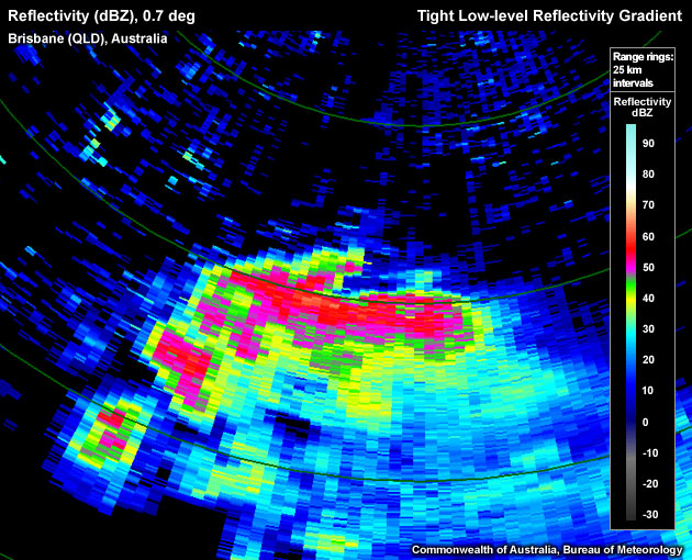
Tight low–level reflectivity gradient on northern flank of storm.
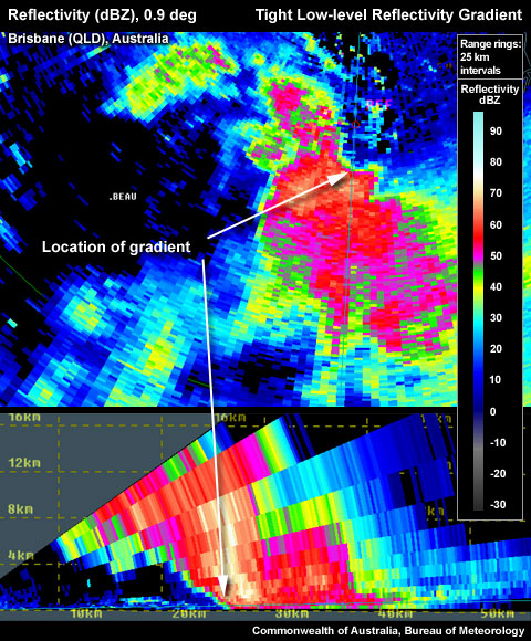
Very tight low-level reflectivity gradient on northern flank of the storm.
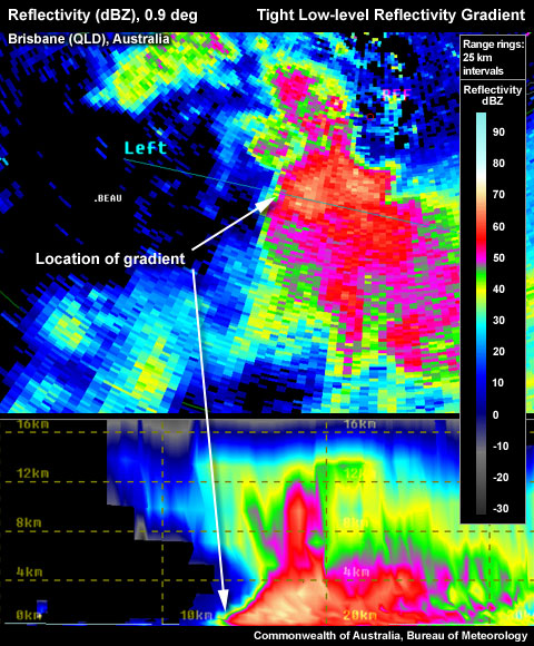
Very tight low-level reflectivity gradient on northern flank in PPI, left hand side in RHI.
Tight Low-level Reflectivity Gradient Look–a–likes
A segment of the edge of the low level core displays a tight low-level reflectivity gradient but is not located on the updraft/inflow side. The important characteristics required to confirm a Tight Low-level Reflectivity Gradient is that the gradient is located on the updraft/inflow quadrant of the thunderstorm and that the signature is persistent in time.
False Tight Low-level Gradient on left hand side in PPI. RHI shows no upper level core above tight gradient. Wrong location for a gradient that is to be used as a proxy for storm severity.
Proper location of Tight Low-level Gradient on northern side in PPI. RHI confirms with upper level core aloft.
Conceptual Model
A Tight Low-level Reflectivity Gradient on the inflow flank is used as one of many signatures pointing towards a severe thunderstorm. The presence of a tight gradient indicates that large hail and/or heavy rainfall is sharply separated from the low–level updraft. The gradient is caused by size sorting of precipitation and the inflow preventing descent of precipitation into the inflow and updraft, suggesting the presence of a strong updraft and a strong downdraft. This increases the chances of occurrence of all four convective hazards, especially large hail and damaging winds.
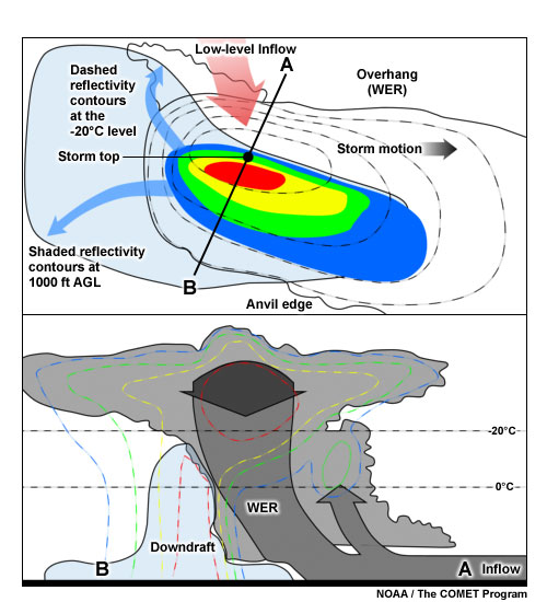
A conceptual model of the structure of a weak echo region within a thunderstorm. The top image shows a plan view of the storm at low level (shaded reflectivity contours) and the –20°C level (dashed reflectivity contours). The blue arrows represent the upper divergence. The red arrow represents the inflow. The lower image shows a cross section of the storm, with the reflectivity contours dashed. The grey arrows represent the updraft with the blue shaded region the downdraft.
Determining Thunderstorm Classification
To help determine the classification of the thunderstorm you are observing, use the following flow chart to help diagnose which thunderstorm conceptual model you should consider more closely.
Diagnosis
Once you have confidently identified a "tight low-level reflectivity" signature, this section will help you estimate the storm severity associated with it. Generally, the spatial and temporal scales of a signature are loosely related to the updraft strength. In other words, the larger and/or more long–lived the signature, the stronger the updraft that produced it. In velocity–based signatures, updraft severity can usually also be gauged by the magnitude of the measured radial velocities. Examining a storms overall temporal evolution will suggest whether the storm is becoming more or less severe. Radar signatures and associated storm developments can also be time–shifted relative to each other, as is the case in supercell tornadoes that occur during the collapse of the parent storm.
When comparing signatures to diagnose relative severity, keep in mind that it is assumed that signatures are sampled at equal ranges from the radar. Otherwise, a storm sampled at greater range (with a wider beam) can appear to be weak and/or weakening, while a storm sampled at a closer range (with a narrower beam) can appear to be strong and/or strengthening.
Degree of Severity
- Gradient strength – Larger changes in reflectivity over a specific distance (stronger gradients) typically indicate stronger updrafts. For example, a stronger updraft is required to size sort 70 dBZ radar targets, as opposed to only 50 dBZ targets.
Weaker low-level reflectivity gradient on northern flank in PPI, left hand side in RHI.
Very tight low-level reflectivity gradient on northern flank in PPI, left hand side in RHI.
- Longevity of the gradient – The more persistent the presence of the tight gradient, the more likely that the this thunderstorm is long–lived and able to continually feed the updraft with a strong inflow.
Considering all these aspects of a Tight Low-level Reflectivity Gradient signature will help to determine overall whether you are dealing with a significant reflectivity gradient signature. In the context of a severe thunderstorm warning decision, a very tight gradient should be counted as good evidence of a severe thunderstorm, but should be used in conjunction with other signatures. Radar data should never be used in isolation and should always be considered in conjunction with the nea- storm environmental information and any observer reports.
Most Likely Convective Hazards
- Damaging winds – a tight low-level reflectivity gradient is a representation of a strong updraft, with potential to produce a strong downdraft.
- Large hail – a strong updraft has the potential to produce large hail, providing the updraft extends past the freezing layer, to –10 to –30 °C layer. Some consideration of the temperature of the environment between the thunderstorm base and the ground is useful to identify the potential for hail melting on its descent to the ground.
See Conceptual Models for more details on why particular severe weather should be included.
References/Addendum
Duda, J.D. and W. A.Gallus Jr., 2010: Spring and Summer Midwestern Severe Weather Reports in Supercells Compared to Other Morphologies. Weather and Forecasting, 25, 190–206.