«- back to print version table of contents
Mesoscale Convective Systems (MCSs) Conceptual Model
Definition of Mesoscale Convective Systems
Large multicell storms consist of a large number of individual cells in close proximity to each other so that they interact in some way. These individual cells might share a common precipitation volume, cloud material or cold pool. New cells usually initiate before older cells dissipate, which means that the mesoconvective system (or mesoscale convective system, more commonly known as MCS) tends to live considerably longer than an individual updraft, usually on the scale of many hours. New cells may initiate more frequently on a preferred flank in organised mesoconvective systems, or initiation may be unorganised and/or sporadic on different flanks.
In contrast to small storm-scale multicells, MCSs uniquely exhibit areas of stratiform precipitation, large anvil shields and system-wide mesoscale flow and morphological features. Given their size and longevity, the Coriolis force is also a significant mechanism that influences the morphology of MSCs.
This section provides information on meso-β scale (20-200 km) and meso-α scale (200-2000 km) systems of thunderstorms (Orlanski 1975). The definitions presented herein are a generalization of Houze (1993). In this section we consider MCSs in all deep layer shear environments. Among the factors that determine the appearance and behaviour of MCSs are the cold pool, the vertical shear, the ambient instability, storm-relative winds, the forcing (physical process associated with initation of new deep updrafts) and many others. We will focus on the cold pool strength as one of the more influential drivers in this context.
Weak Cold Pool Systems
Larger multicells generally have a tendency to evolve into cold pool dominant systems. However, the following two classes of multicell systems form a more common exception.
Elevated MCS
MCSs can occur in the presence of a conditionally stable layer of air near the ground. In that case inflow parcels are sourced from well above the ground. The pre-existing stable layer of air makes it difficult to form a strong cold pool near the surface that drives the system behaviour.
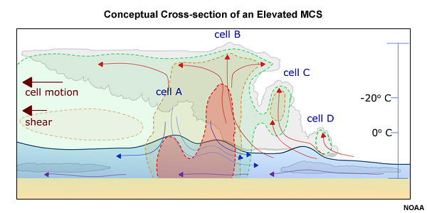
Fig. 1: Conceptual cross-section of an elevated MCS with shaded reflectivity contours. Note that the system's downdrafts do not reach the surface, but may undergo gravity wave-type oscillations after entering the stable layer near the ground. The near-surface air (purple arrows) is not interacting with the elevated muticell.
Tropical Cyclones
A second way of preventing the formation of a strong cold pool in the presence of an MCS is to limit the potential for downdraft cooling through evaporation and sublimation or to somehow warm up a pre-cooled downdraft. The former can be achieved in boundary layers with very high relative humidities, the latter through the injection of low-level diabatic heating from, for example, a very warm ocean surface such as a tropical ocean. Such environments are necessary for the formation of tropical cyclones, a special type of MCS of sufficient duration and spatial extent so that the Coriolis force and pressure gradient forces associated with a distinct region of low pressure within the centre of the system become two of the dominant forces at work.
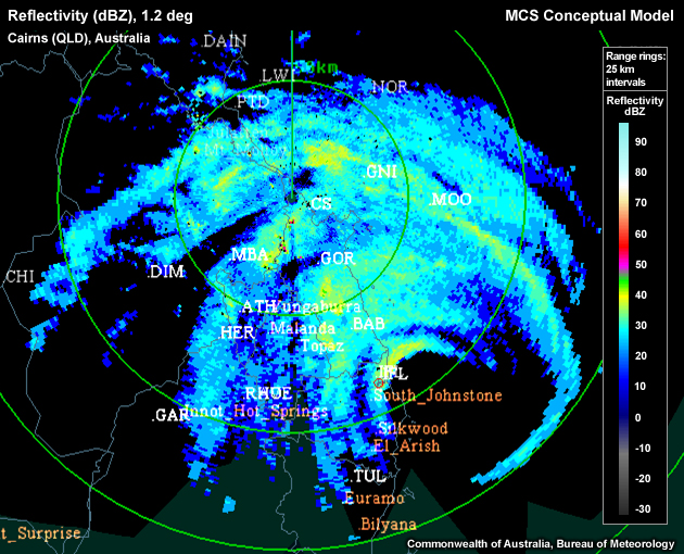
Fig. 2: Radar reflectivity image of tropical cyclone Larry around the time of landfall in Queensland on 19 March 2006. The cyclone's eye is apparent about 100 km southeast of the radar location.
Strong Cold Pool Systems
Most observed MCSs can be found near the strong cold pool end of the spectrum with a typical evolution and structure conceptualised in Fig. 1, which shows a linear MCS with a trailing stratiform precipitation region (by far the most common type).
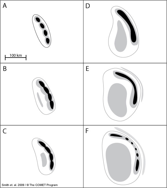
Fig. 3: Conceptual radar evolution of a typical summertime midlatitude MCS in the southern hemisphere. Black shading represents radar reflectivities of 50 dBZ and above, gray shading represents 35–50 dBZ and the gray outline represents the 0-dBZ echo boundary. A storm such as this one may evolve from initial cells like those in panel A to a decaying MCS like that pictured in panel F in as little as several hours or as long as a day. Typically, after the initial cells begin to merge in panel A, one to three hours will elapse between each stage shown in the subsequent panels.
A continuous or broken line of deep, active convection begins to form the leading edge of an MCS. This line may initially consist of ordinary cells or severe, individually organised cells, and sometimes even embedded supercells (Fig. 3A). Usually, a region of stratiform precipitation develops from hydrometeors advected rearward from the active convection region via ascending, front-to-rear flowing upper level winds (Fig. 3B-D and Fig. 4).
Precipitation formation results in substantial latent heat release, especially in high CAPE and high shear environments. High CAPE environments are marked by a substantial difference between updraft parcel and ambient temperature, which yields a stronger hydrostatic low. High deep-layer shear environments create stronger individual updrafts with a higher mass, and therefore also yield stronger latent heat release. The most latent heat is released within the "thick" part of the stratiform anvil, near the line of active convection. This release hydrostatically induces low pressure below the anvil along the top edge of the cold pool (marked by mesoscale lows "L3" and "L4" in the line-perpendicular cross section in Fig. 4 below). This in turn sets up a horizontal pressure gradient near the upper part of the cold pool that primarily accelerates the system-relative rear-to-front flow until it reaches the leading edge of the system.
Fig. 4: Conceptual vertical cross-section of a trailing stratiform Mesoscale Convective System (MCS) adapted from Houze et al (1989). Not all of the following features are present in all systems: A "wake" low (L1) occurs at the surface of the back edge of the stratiform rain, in association with warming due to unsaturated descent, and a mesohigh (H1) occurs below the convective region. A weak mesolow (L2), associated with warming by compensating downward motion is often noted ahead of the convective line at the surface. In the midtroposphere a small, apparently hydrostatic mesolow (L3) is located below the primary sloping buoyant convective updraft. In the vicinity of the melting or just above, is another mesolow (L4) that is larger in scale. A mesohigh at upper levels (H2) atop the mesoscale system becomes particularly well marked in the case of mesoscale convetive complexes.
The system-relative descending rear inflow, when strong, is often referred to as a Rear Inflow Jet (RIJ). Modeling efforts by Weisman (1992) have further described how opposing circulations induced by the front-to-rear flow and the cold pool below affect the acceleration of the RIJ.
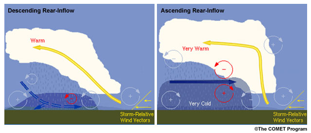
Fig. 5: Schematic of an MCS with a descending (left) and non-descending (right) rear-inflow jet as a result of horizontal vorticity balance arguments based on Weisman (1992).
RIJs tend to slope downward as they approach the leading edge of the MCS, in part due to precipitation evaporating as it falls into the drier rear inflow. RIJs may be descending or non-descending (Fig. 5). The degree of RIJ descent is one of the predictors of MCS longevity and intensity (Weisman 1992).
In environments of weaker vertical shear (less than 30 kts over the cold pool-depth) and lower CAPE values (< 1000 J/kg), the cold pool circulation tends to dominate the anvil circulation, which forces the RIJ towards the surface in the left panel of Fig. 5. Near the leading edge of the cold pool, the near-surface RIJ now reinforces the cold pool circulation which further reinforces the circulation imbalance and also enhances the forward motion of the system cold pool relative to the leading updrafts. The result is a weakening MCS.
In contrast, higher CAPE and stronger (low-level) shear environments strengthen the updraft and hence the rearward anvil circulation (right panel of Fig. 5) so that the anvil circulation is more likely to match the opposing cold pool circulation. This balance leads to a non-descending RIJ which is associated with a circulation that now opposes the cold pool counterpart near the leading edge of the cold pool. The result is a deeper gust front that is less likely to outrun the leading edge convection of the MCS, and therefore a longer-lived system. Of additional benefit to MCS longevity would be a steering flow that closely matches the gust front speed such that initiating updrafts have the ability to remain in the gust front's lifting zone for an extended period of time.
Note that the RIJ behaviour is not the only predictor of MCS longevity or intensity. The vertical shear profile above the cold pool exerts control over the gust front-relative storm motion and therefore MCS longevity (Shapiro 1992; Xue 2000; Coniglio and Stensrud 2001). Other predictors suggested by Evans and Doswell (2001) are the strength of the midlevel winds, the magnitude of the low-level storm-relative flow and the deep-layer shear.
MCS Structure on Radar
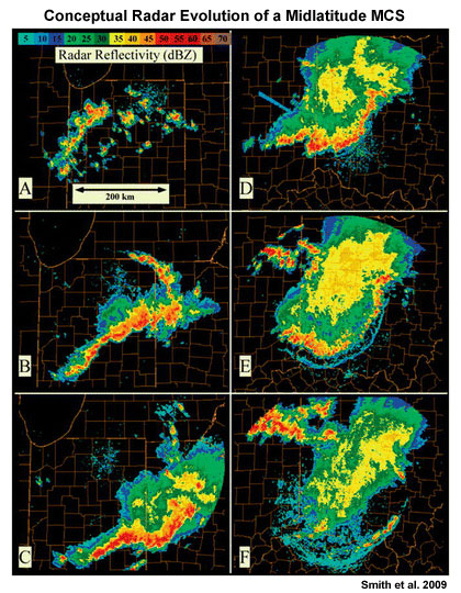
Fig. 1: Typical radar evolution of a linear, trailing stratiform MCS in the United States. Shortly after initiation, a cluster of isolated cells (A) starts to form a large, combined cold pool which leads to the formation of a more continuous line of deep convection (B,C). Over time, a trailing stratiform precipitation region forms (C,D). A system-scale gust front begins to outrun the leading line of active convection (D,E) which ultimately leads to the demise of that line. A new line of convection initiates along the runaway gust front in (F).
Fig. 1 above illustrates the overall evolution of a typical linear, trailing stratiform MCS as well as some of the attendant radar signatures that can be used to identify the potential and/or occurrence of damaging surface winds. These, and other signatures and severe wind phenomena that are commonly associated with linear MCSs, are summarized below.
Bow Echo (Fig. 1, panels C-F)
Fujita (1978) observed symmetric bow-shaped convective line segments 20-120km long that tended to produce extended swaths of damaging surface winds and first referred to them as "bow echoes." In most cases either a very strong rear-inflow jet or a strong downdraft deforms the leading active line of convection into a bow-shaped arrangement. While bow echoes, a special type of severe linear MCS, can occur over a wide range of shear and instability regimes, they most commonly occur in high CAPE and high shear environments and possess deep, slab-like lifting along the bowed-out gust front of a strong cold pool. Bow echoes can evolve as an accelerating segment of a squall line, or from a single strong storm (usually a high precipitation supercell; Finley et al. 2001). The transition into a bow is usually on the order of an hour or two.
Rear Inflow Notch
A rear-inflow notch (RIN), which marks an evaporatively cooled strong rear-inflow jet (Przybylinski and Schmocker 1993; see Fig. 2) is often evident just before and during the leading line's initial transformation into a bow echo.
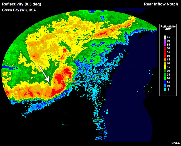
Fig. 2: Rear inflow notch evident as an area of weakened reflectivities behind a newly-formed bow echo in the north-central United States.
Bookend Vortices
The mature bow echo often contains one or two bookend vortices. Bookend vortices generally mark a region of enhanced downdraft and an increased probability of stronger winds at the surface. The distance between both bookend vortices is one measure of the likely strength of the RIJ, with smaller distances associated with stronger RIJs (Weisman 1992). Line-end vortices tend to drift rearward (relative to the MCS) in weaker shear environments, but are more likely to stay with the leading edge of convection in stronger shear environments. For a sufficiently persistent MCS, the Coriolis force eventually leads to a strengthening of the cyclonic (or poleward) bookend vortex and a weakening of the anticyclonic (or equatorward) vortex. In that case the MCS eventually assumes a comma-shaped appearance (comma echo).
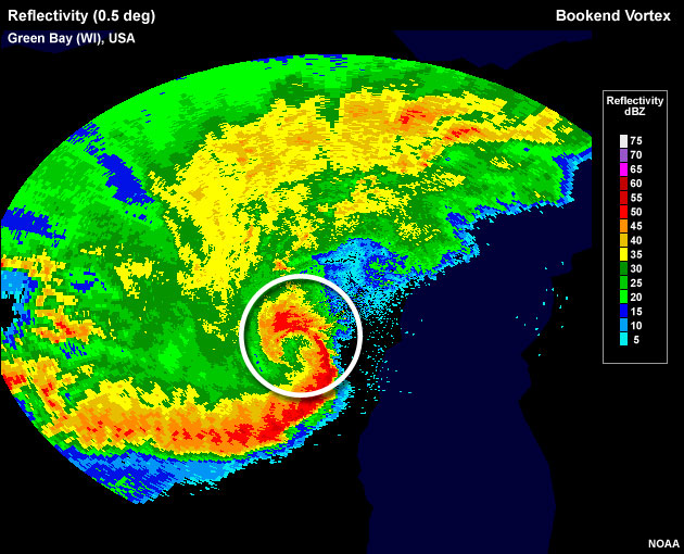
Fig. 3: Mature bow echo over Green Bay (Wisconsin, USA) showing a well-developed bookend vortex at the poleward end of the MCS.
While the strongest winds commonly occur at the bow's apex, bow echoes can also contain weak tornadoes, or mesovortices, along the leading edge of the bow usually near and poleward of the bow's apex (Atkins et al. 2005; Atkins and Laurent 2009a,b).
A bow echo's motion vector is controlled by the propagation of the strong cold pool with bow echoes tending to move much faster than other surrounding multicells.
Derechoes
A long-lasting (up to a day) severe wind event that extends over at least 250 nm (463 km) and contains multiple 65+ kts (33.5 m/s) wind gusts has been observed and first defined as a derecho in Johns and Hirt (1987). Such events are usually produced by a sequence of one or more severe bow echoes. Often the damaging winds occur within several distinct episodes.
While derechoes can occur over a wide range of shear and instability regimes, they most commonly occur in an environment with strong deep layer shear combined with high CAPE, steep midlevel lapse rates and a strong system cold pool. Of importance for discriminating derecho from non-derecho environments are the strength of the 0-6km mean winds and the 0-2 km system-relative flow, the latter being mostly due to the fast system speed itself (Evans and Doswell 2001).
Derechoes occur either as progressive derechoes, where short bow echo segments move along a quasi-stationary front (Fig. 4, Progressive Derecho), or as serial derechoes where a squall line moves approximately at right angles to the steering flow and contains individual severe bow echoes that rapidly move along the line and with the steering flow (Fig. 4, Serial Derecho).
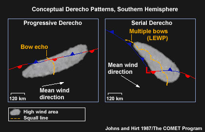
Fig. 4: Conceptualisation of the two derecho types. The orange line segment marks a typical instantaneous snap shot of the active convection.
Radar animation of a derecho that caused widespread damage as it moved over Oklahoma and Texas, United States. The animation shows 10 hours of the system's lifetime.
Other Radar Indicators of Damaging Winds in MCSs
Two MCS regions that pose an increased threat of damaging winds are squall line segments where the gust front stays close to the leading edge of the low-level reflectivity core, and segments with strong low-level reflectivity gradients.
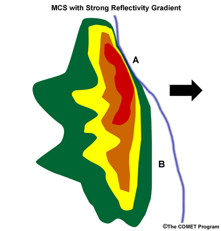
Fig. 5: Conceptual model of an MCS moving left to right. Shown qualitatively as a low-level horizontal slice through the radar reflectivity of the system. The blue line ahead of the low-level reflectivity core marks the system gust front. Point A shows a gust front that stays close to the leading deep updrafts of the system and a tight low-level reflectivity gradient. Both indicators suggest an enhanced likelihood for damaging winds near point A. Point B shows a gust front that has outrun the core, and a very broad reflectivity gradient. The damaging wind risk here is significantly lower that at point A.
In any event, it is useful to search for additional radar-based evidence of individual cell severity, such as the presence of a Weak Echo Region (WER) in the vicinity of point A in Fig. 5 above.
As one approach for forecasting the onset of damaging surface winds, a system-relative velocity image might show a Mid-Altitude Radial Convergence or MARC signature near the leading edge of the midlevel intense reflectivity core of the system as a precursor to the descent of an elevated RIJ (Przybylinski et al. 1995) and therefore as a precursor to the onset of damaging winds on the surface.
Use the radio buttons or click the image to switch between reflectivity and velocity imagery:
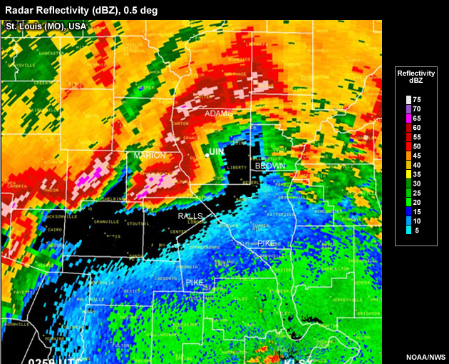
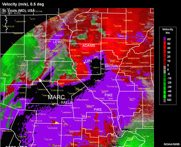
Radar reflectivity and storm-relative velocity image of a bow echo that exhibits a Mid-Altitude Radial Convergence (MARC) signature. Elevation of beam at location of signature is approximately 11,500 ft AGL.
MCS Environment and Propogation
Although MCSs usually develop into a linear mode with a trailing stratiform (TS) region, parallel stratiform (PS) region MCSs or leading stratiform (LS) region MCSs also commonly occur, as outlined below by Parker and Johnson (2000).
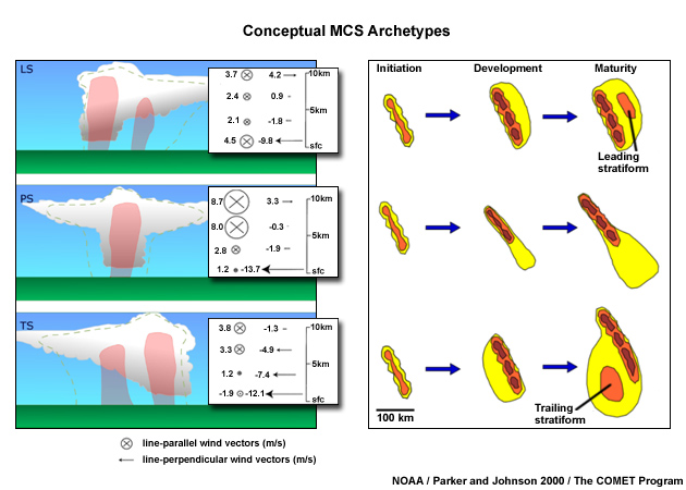
A schematic of three MCS archetypes described in Parker and Johnson (2000). The left side shows vertical profiles of layer-mean storm-relative pre-MCS winds for linear MCS classes. Wind vectors are depicted as line-parallel (X) and line-perpendicular (→) components in m/s. Layers depicted are 0–1, 2–4, 5–8, and 9–10 km The right side of the figure shows the idealised radar reflectivity patterns for each of the three MCS types. Note that the mature reflectivity pattern for the thunderstorm type is specific to the southern hemisphere where the influence of the Coriolis force leads to an enhancement of the trailing stratiform precipitation region on the sourthern end of the convective line.
Table 1 briefly outlines the main attributes of the three MCS types, the formation of which is mainly driven by the system-relative flow at various levels:
| Environmental and Storm Characteristics of MCS Archetypes | |||
|---|---|---|---|
| Leading Stratiform (LS) |
Parallel Stratiform (PS) | Trailing Tratiform (TS) | |
| Upper-level system-relative flow | Rear-to-front | Strongly line-parallel | Front-to-rear |
| Lower-level system-relative flow | Front-to-rear and parallel | Strongly front-to-rear | Strongly front to rear |
| Cold Pool Strength | Weak | Moderate | Strong |
| CAPE (J/kg) | 1009 | 813 | 1605 |
| Propagation Speed (m/s) | 7.1 | 11.4 | 13.0 |
| Mean Duration (h) | 6.5 | 6.3 | 12.2 |
| Occurrence (% of all MCSs) | 20% | 20% | 60% |
Table 1: Outline of various attributes of linear MCSs. Adapted from Parker and Johnson (2000).
MCS Propagation
Frequently, multicells don't move simply with the steering flow (i.e., the mass-weighted mean wind in the cloud-bearing layer). Their motion vector possesses a propagation component that is controlled by new cell initiation on a preferred flank; this is particularly true for more organised multicells. Figure 1 shows four of the more influential physical mechanisms that set up such a preferred flank with regard to an existing cold pool.
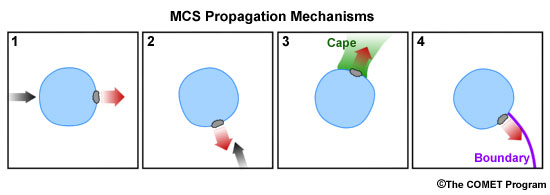
Fig. 1: Conceptual depiction of four of the more prominent physical processes that create a preferred flank for the initiation of new updrafts along a multicell's cold pool boundary. Such directionally selective cell initiation then controls the system's propagation component of the overall motion vector (remember: motion = steering + propagation).
The four mechanisms shown are:
1: Downshear Propagation
2: Propagation Due to Low-level Convergence
3: Propagation into an Axis of Surface-based Instability
4: Propagation Due to Boundary Interactions
At times, more than one of the propagation mechanisms may simultaneously affect a single multicell, which can even lead to splitting of the original system.
Base Propagation Case: No Low-level Shear
Based on idealised numerical simulations, Rotunno et al. (1988) found in the case of zero low-level shear that the relatively warm air outside a cold pool boundary would only be lifted to the top of and then across the cold pool. If the cold pool depth exceeds the local level of free convection (fig. 2: LFC 1, so D>LFC1), initiation would ensue at a random location along the cold pool boundary. If the local LFC is located well above the cold pool depth (LFC 2, with D<LFC 2) the lifting would remain too shallow for initiation.
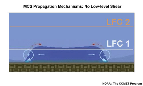
Fig. 2: Conceptual model identifying no preferred flank for new cell initiation along the cold pool edge of an existing multicell in a no shear scenario as outlined in Rotunno et al. (1988).
Propagation Mechanism 1: Downshear Propagation
In the case of nonzero low-level shear over the cold pool depth (say, 3 km) the circulations associated with the cold pool as well as the shear profile interact constructively to generate the deepest lifting of surface parcels on the downshear side of the cold pool. If the lifting is deep enough to reach the local LFC (fig. 3: LFC 2; fig. 2: LFC 1) new initiation is possible.
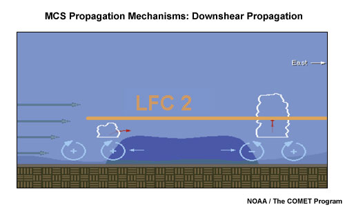
Fig. 3: Conceptual model identifying the preferred flank for new cell initiation along the cold pool edge of an existing multicell in an environment containing low-level shear as outlined in Rotunno et al. (1988).
An assumption here is that both circulations are of approximately similar magnitudes (cold pool-shear balance). When applying this concept, two issues to consider are the fragility of maintaining the circulation balance between the cold pool and the low-level shear, and the potential influence of other lifting mechanisms outlined below.
Propagation Mechanism 2: Propagation Due to Low-level Convergence
The location where a strong low-level jet impinges upon the cold pool boundary is likely to exhibit strong low-level convergence and parcel lifting over the cold pool. Such lift makes this location a preferred flank for initiation and should therefore lead to a system propagation component (-J) into the low-level jet.
Corfidi et al. (1996; 2003) attempt to quantify the overall system motion for MCSs (fig. 4 A) subject to the described type of propagation process. To match observed multicell motion vectors (V), the studies make a distinction between upwind and downwind-propagating systems. For upwind-propagating multicells, the total motion vector V is the vector sum of the steering flow S and the negative of the low-level storm-relative flow –J. For downwind-propagating multicells (fig. 4 B), we can approximate V as the sum of twice the steering flow and the negative of the low-level storm-relative flow.
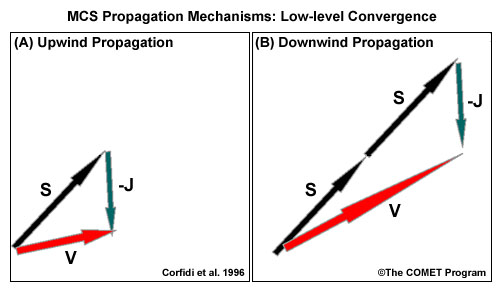
Fig. 4: Estimated total motion vector V for upwind-propagating (A) and downwind-propagating (B) MCSs based on Corfidi et al. (1996). S marks the steering flow (mass-weighted mean wind in the cloud-bearing layer), and -J marks the negative of the maximum low-level storm-relative flow.
The forecast/nowcast application of the total multicell motion vector V estimate should help in the appraisal of the flash flood risk for back-building systems (more likely in case A, upwind propagation) or the risk of damaging winds for forward-propagating systems where steering and propagation vectors are additive (more likely in case B, downwind propagation). Generally, even initially backward propagating systems eventually mature into forward-propagating ones as their cold pool strengthens.
Propagation Mechanism 3: Propagation into an Axis of Surface-based Instability
In a modelling study, Richardson (1999) found that an axis of high surface dewpoints (equating to lower LFCs) intercepting a cold pool boundary leads to a preferred flank for new cell initiation as shallower lifting depth is sufficient here to initiate new cells. This preference can lead to the multicell propagating into the instability axis.
Propagation Mechanism 4: Propagation Due to Boundary Interactions
The intersection points of boundaries, such as a multicell cold pool boundary and some external convergence lines, are preferred points for new initiation (Purdom 1976; Wilson and Schreiber 1986; Fankhauser et al. 1995; Hane et al. 1997; Koch and Ray 1997; Mahoney 1988). Such new "triple point" convection would likely produce a cold pool that merges with the cold pool of the original multicell and could lead to the original multicell being "anchored" to the triple point so that it follows that point's motion instead of moving with the steering flow (Weaver 1979).
Hazards Associated with MCSs
Damaging Winds
As deep convection grows upscale and its cold pool strengthens over time, the threat of damaging winds becomes the primary convective hazard to consider. In particular, bow echoes and derechoes can be responsible for damaging and destructive straight line winds. Preferred locations for strong surface winds are:
- Along the axis of a descending rear-inflow jet (often the apex of a bowing echo)
- Near stronger reflectivity cores along the leading line of active convection especially if the gust front stays close to that core
Tornadoes
Tornadoes are possible with MCSs, either in the form of supercell tornadoes associated with individual embedded supercells within an MCS, or in the form of mesovortices along the leading edge of a convective line. Preferred location for such mesovortices are near the apex of a bowing core segment and along the poleward side of that apex.
Hail
The hail threat diminishes as deep convection grows upscale and as ambient instability is more quickly consumed by the larger number of updrafts present in an MCS. Embedded severe cells, often found at the end of a convective line or near gaps within that line, are the likeliest places for marginally severe hail to fall.
Flooding
MCSs can be very potent flash flood producers, especially in the following circumstances:
- Slow-moving
- Large in size
- Moving across the same locations for an extended period of time
- When backbuilding
Rather than the instantaneous rainfall rate, it is the exposure time to moderately heavy rain that ultimately drives the flash flood threat. It is advisable in these situations to closely monitor the rainfall accumulations at those locations that have been experiencing rainfall over an extended period of time.
References/Addendum
Atkins, N. T., C. S. Bouchard, R. W. Przybylinski, R.J. Trapp, Gg Schmocker, 2005: Damaging Surface Wind Mechanisms within the 10 June 2003 Saint Louis Bow Echo during BAMEX. Monthly Weather Review, 133: 2275-2296.
Atkins, N. T., and M. St. Laurent, 2009: Bow Echo Mesovortices. Part I: Processes That Influence Their Damaging Potential. Monthly Weather Review, 137: 1497-1513.
Atkins, N. T., and M. St. Laurent, 2009: Bow Echo Mesovortices. Part II: Their Genesis Nolan T. Atkins, Michael St. Laurent. Monthly Weather Review, 137: 1514-1532.
Coniglio, M. C., and D. J. Stensrud, 2001: Simulation of a Progressive Derecho Using Composite Initial Conditions. Monthly Weather Review, 129: 1593-1616.
Coniglio, M. C., H. E. Brooks, S. J. Weiss, S. F. Corfidi, 2007: Forecasting the Maintenance of Quasi-Linear Mesoscale Convective Systems. Weather and Forecasting, 22: 556-570.
Corfidi, S.F., J.H. Merritt, and J.M. Fritsch, 1996: Predicting the movement of mesoscale convective complexes. Wea. Forecasting, 11, 41-46.
Corfidi, Stephen F. 2003: Cold Pools and MCS Propagation: Forecasting the Motion of Downwind-Developing MCSs. Wea. Forecasting, 6: 997–1017.
Doswell, C. A., and J. S.Evans, 2001: Examination of Derecho Environments Using Proximity Soundings. Weather and Forecasting, 16: 329-342.
Fankhauser, J.C., N.A. Crook, J. Tuttle, L.J. Miller, C.G. Wade, 1995: Initiation of deep convection along boundary layer convergence lines in a semitropical environment. Monthly Weather Review, 123: 291–314.
Finley, Catherine A., Cotton, W. R., Pielke, R. A.. 2001: Numerical Simulation of Tornadogenesis in a High-Precipitation Supercell. Part I: Storm Evolution and Transition into a Bow Echo. J. Atmos Sci., 58: 597–1629.
Fujita, T.T., 1978: Manual of downburst identification for project NIMROD. SMRP Research Paper No. 156, pp 104.
Hane, . E., H. B. Bluestein, T. M. Crawford, M. E. Baldwin, R. M. Rabin, 1997: Severe Thunderstorm development in relation to along dryline variability: A case study. Mon. Wea. Rev., 125: 231–251.
Houze, R. A., Jr., M. I. Biggerstaff, S. A. Rutledge, B. F. Smull, 1989: Interpretation of Doppler Weather Radar Displays of Midlatitude Mesoscale Convective Systems. Bulletin of the American Meteorological Society, 70: 608-619.
Houze, R. A., Jr., 1993: Cloud Dynamics. Academic Press, pp 573.
Johns, R. H., and W. D. Hirt, 1987: derechoes: Widespread Convectively Induced Windstorms. Weather and Forecasting, 2: 32-49.
Koch, S, and C. A. Ray, 1997: Mesoanalysis of summertime convergence zones in central and eastern North Carolina. Wea. Forecasting, 12: 56–77.
Mahoney, W.P. III, 1988: Gust front characteristics and the kinematics associated with interacting thunderstorm outflows. Mon. Wea. Rev., 116: 1474-1491.
Przybylinski, R. W., and G.K. Schmocker, 1993: The evolution of a widespread convective wind storm event over central and eastern Missouri. Preprints, 13th Conf. On Weather Analysis and Forecasting, Vienna, VA, Amer. Meteor. Soc., 461-465.
Przybylinski, R. W., and Y.-J, Lin, G.K. Schmocker, and T.J. Shea, 1995: The use of real-time WSR-88D, profiler, and conventional data sets in forecasting a northeastward moving derecho over eastern Missouri and central Illinois. Preprints, 14th Conf. on Wea. Analysis and Forecasting, Dallas, Amer. Meteor. Soc., 335-342.
Rotunno, R., J. B. Klemp, M. L. Weisman, 1988: A Theory for Strong, Long-Lived Squall Lines. Journal of the Atmospheric Sciences, 45: 463-485.
Shapiro, A. 1992: A hydrodynamical model of shear flow over semi-infinite barriers with application to density currents. J. Atmos. Sci., 49, 2293–2305.
Smith, A. M., G. M. McFarquhar, R. M. Rauber, J. A. Grim, M. S. Timlin, B. F. Jewett, D. P. Jorgensen, 2009: Microphysical and Thermodynamic Structure and Evolution of the Trailing Stratiform Regions of Mesoscale Convective Systems during BAMEX. Part I: Observations. Monthly Weather Review, 137: 1165-1185
Weisman, M. L., 1992: The Role of Convectively Generated Rear-Inflow Jets in the Evolution of Long-Lived Mesoconvective Systems. Journal of the Atmospheric Sciences, 49: 1826-1847.
Weisman, M. L., 1992: The Genesis of Severe, Long-Lived Bow Echoes. Journal of the Atmospheric Sciences, 50: 645-670.
Xue, M. 2000: Density currents in two-layer shear flows. Quart. J. Roy. Atmos. Sci., 126: 1301–1320.