
Definition of Mesoscale Convective Systems
Large multicell storms consist of a large number of individual cells in close proximity to each other so that they interact in some way. These individual cells might share a common precipitation volume, cloud material or cold pool. New cells usually initiate before older cells dissipate, which means that the mesoconvective system (or mesoscale convective system, more commonly known as MCS) tends to live considerably longer than an individual updraft, usually on the scale of many hours. New cells may initiate more frequently on a preferred flank in organised mesoconvective systems, or initiation may be unorganised and/or sporadic on different flanks.
In contrast to small storm-scale multicells, MCSs uniquely exhibit areas of stratiform precipitation, large anvil shields and system-wide mesoscale flow and morphological features. Given their size and longevity, the Coriolis force is also a significant mechanism that influences the morphology of MSCs.
This section provides information on meso-β scale (20-200 km) and meso-α scale (200-2000 km) systems of thunderstorms (Orlanski 1975). The definitions presented herein are a generalization of Houze (1993). In this section we consider MCSs in all deep layer shear environments. Among the factors that determine the appearance and behaviour of MCSs are the cold pool, the vertical shear, the ambient instability, storm-relative winds, the forcing (physical process associated with initation of new deep updrafts) and many others. We will focus on the cold pool strength as one of the more influential drivers in this context.
Weak Cold Pool Systems
Larger multicells generally have a tendency to evolve into cold pool dominant systems. However, the following two classes of multicell systems form a more common exception.
Elevated MCS
MCSs can occur in the presence of a conditionally stable layer of air near the ground. In that case inflow parcels are sourced from well above the ground. The pre-existing stable layer of air makes it difficult to form a strong cold pool near the surface that drives the system behaviour.
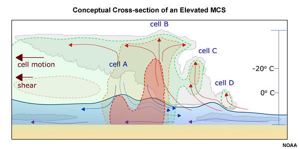
Fig. 1: Conceptual cross-section of an elevated MCS with shaded reflectivity contours. Note that the system's downdrafts do not reach the surface, but may undergo gravity wave-type oscillations after entering the stable layer near the ground. The near-surface air (purple arrows) is not interacting with the elevated muticell.
Tropical Cyclones
A second way of preventing the formation of a strong cold pool in the presence of an MCS is to limit the potential for downdraft cooling through evaporation and sublimation or to somehow warm up a pre-cooled downdraft. The former can be achieved in boundary layers with very high relative humidities, the latter through the injection of low-level diabatic heating from, for example, a very warm ocean surface such as a tropical ocean. Such environments are necessary for the formation of tropical cyclones, a special type of MCS of sufficient duration and spatial extent so that the Coriolis force and pressure gradient forces associated with a distinct region of low pressure within the centre of the system become two of the dominant forces at work.
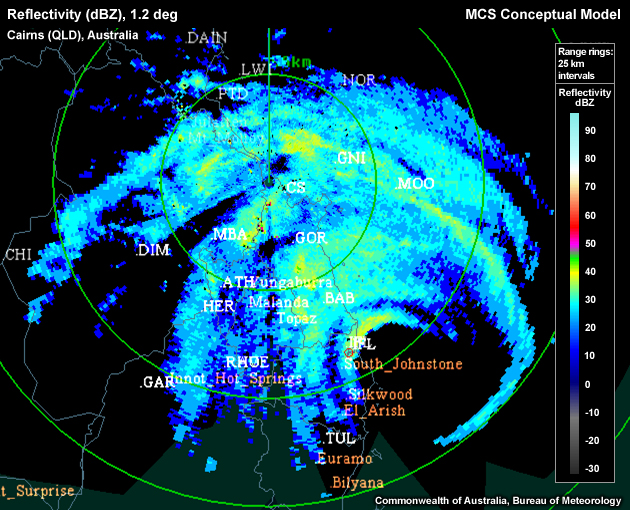
Fig. 2: Radar reflectivity image of tropical cyclone Larry around the time of landfall in Queensland on 19 March 2006. The cyclone's eye is apparent about 100 km southeast of the radar location.
Strong Cold Pool Systems
Most observed MCSs can be found near the strong cold pool end of the spectrum with a typical evolution and structure conceptualised in Fig. 1, which shows a linear MCS with a trailing stratiform precipitation region (by far the most common type).
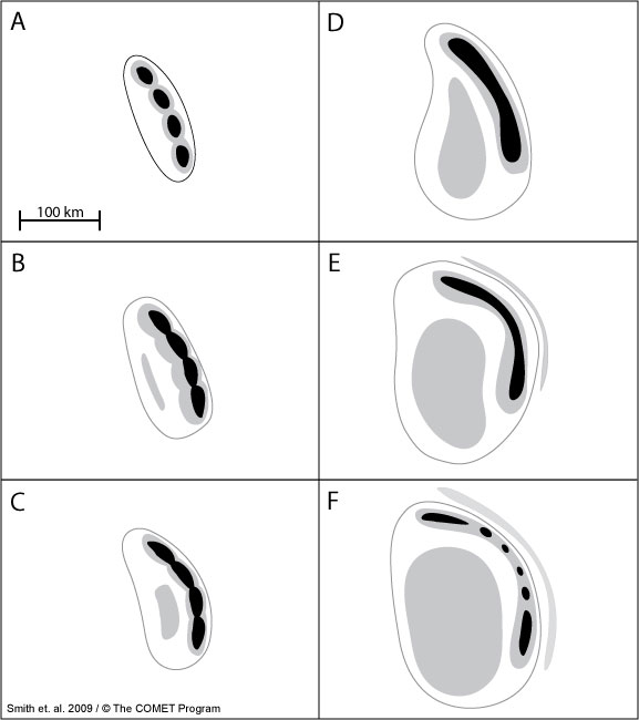
Fig. 3: Conceptual radar evolution of a typical summertime midlatitude MCS in the southern hemisphere. Black shading represents radar reflectivities of 50 dBZ and above, gray shading represents 35–50 dBZ and the gray outline represents the 0-dBZ echo boundary. A storm such as this one may evolve from initial cells like those in panel A to a decaying MCS like that pictured in panel F in as little as several hours or as long as a day. Typically, after the initial cells begin to merge in panel A, one to three hours will elapse between each stage shown in the subsequent panels.
A continuous or broken line of deep, active convection begins to form the leading edge of an MCS. This line may initially consist of ordinary cells or severe, individually organised cells, and sometimes even embedded supercells (Fig. 3A). Usually, a region of stratiform precipitation develops from hydrometeors advected rearward from the active convection region via ascending, front-to-rear flowing upper level winds (Fig. 3B-D and Fig. 4).
Precipitation formation results in substantial latent heat release, especially in high CAPE and high shear environments. High CAPE environments are marked by a substantial difference between updraft parcel and ambient temperature, which yields a stronger hydrostatic low. High deep-layer shear environments create stronger individual updrafts with a higher mass, and therefore also yield stronger latent heat release. The most latent heat is released within the "thick" part of the stratiform anvil, near the line of active convection. This release hydrostatically induces low pressure below the anvil along the top edge of the cold pool (marked by mesoscale lows "L3" and "L4" in the line-perpendicular cross section in Fig. 4 below). This in turn sets up a horizontal pressure gradient near the upper part of the cold pool that primarily accelerates the system-relative rear-to-front flow until it reaches the leading edge of the system.
Fig. 4: Conceptual vertical cross-section of a trailing stratiform Mesoscale Convective System (MCS) adapted from Houze et al (1989). Not all of the following features are present in all systems: A "wake" low (L1) occurs at the surface of the back edge of the stratiform rain, in association with warming due to unsaturated descent, and a mesohigh (H1) occurs below the convective region. A weak mesolow (L2), associated with warming by compensating downward motion is often noted ahead of the convective line at the surface. In the midtroposphere a small, apparently hydrostatic mesolow (L3) is located below the primary sloping buoyant convective updraft. In the vicinity of the melting or just above, is another mesolow (L4) that is larger in scale. A mesohigh at upper levels (H2) atop the mesoscale system becomes particularly well marked in the case of mesoscale convetive complexes.
The system-relative descending rear inflow, when strong, is often referred to as a Rear Inflow Jet (RIJ). Modeling efforts by Weisman (1992) have further described how opposing circulations induced by the front-to-rear flow and the cold pool below affect the acceleration of the RIJ.
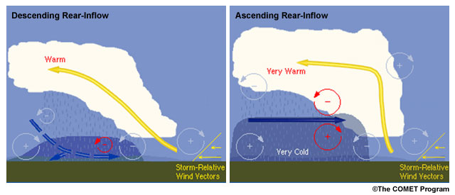
Fig. 5: Schematic of an MCS with a descending (left) and non-descending (right) rear-inflow jet as a result of horizontal vorticity balance arguments based on Weisman (1992).
RIJs tend to slope downward as they approach the leading edge of the MCS, in part due to precipitation evaporating as it falls into the drier rear inflow. RIJs may be descending or non-descending (Fig. 5). The degree of RIJ descent is one of the predictors of MCS longevity and intensity (Weisman 1992).
In environments of weaker vertical shear (less than 30 kts over the cold pool-depth) and lower CAPE values (< 1000 J/kg), the cold pool circulation tends to dominate the anvil circulation, which forces the RIJ towards the surface in the left panel of Fig. 5. Near the leading edge of the cold pool, the near-surface RIJ now reinforces the cold pool circulation which further reinforces the circulation imbalance and also enhances the forward motion of the system cold pool relative to the leading updrafts. The result is a weakening MCS.
In contrast, higher CAPE and stronger (low-level) shear environments strengthen the updraft and hence the rearward anvil circulation (right panel of Fig. 5) so that the anvil circulation is more likely to match the opposing cold pool circulation. This balance leads to a non-descending RIJ which is associated with a circulation that now opposes the cold pool counterpart near the leading edge of the cold pool. The result is a deeper gust front that is less likely to outrun the leading edge convection of the MCS, and therefore a longer-lived system. Of additional benefit to MCS longevity would be a steering flow that closely matches the gust front speed such that initiating updrafts have the ability to remain in the gust front's lifting zone for an extended period of time.
Note that the RIJ behaviour is not the only predictor of MCS longevity or intensity. The vertical shear profile above the cold pool exerts control over the gust front-relative storm motion and therefore MCS longevity (Shapiro 1992; Xue 2000; Coniglio and Stensrud 2001). Other predictors suggested by Evans and Doswell (2001) are the strength of the midlevel winds, the magnitude of the low-level storm-relative flow and the deep-layer shear.