
Detection
A Tight Low-level Reflectivity Gradient refers to the quick gradation from low reflectivities to high reflectivities (storm core) over a few kilometres in the vicinity of the Weak Echo Region (WER) or Bounded Weak Echo Region (BWER), the location of the updraft in a strong thunderstorm.
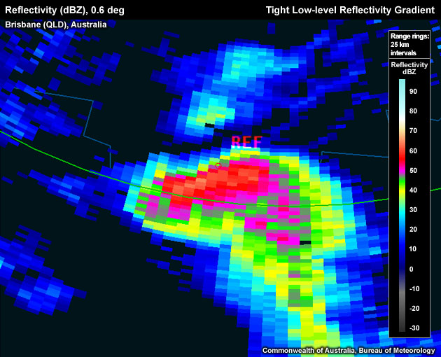
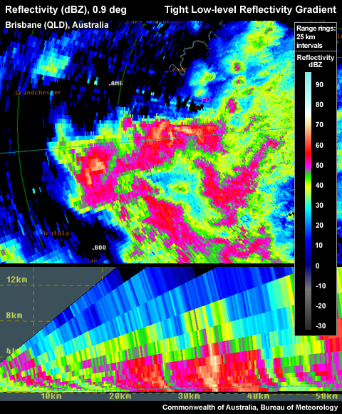
Tight low-level reflectivity gradient on the northern flank of the storm. Note the reference point (storm top) sitting right above the low level gradient.
To determine if the signature you are seeing is a Tight Low-level Reflectivity Gradient use the following technique:
Reflectivity: PPI/Plan View
Determining the inflow/updraft location:
- Step up in elevation scans until you run out of >50 dBZ echoes.
- Step down one elevation scan.
- Centre cursor on the upshear side of >50 dBZ core (this is to account for storm movement during the time that elapsed between the lowest tilt radar scan and the storm top scan).
- Set a reference point.

The reference point (storm top) is located well outside the low–level core.
- Step down to the lowest elevation scan.
- Is there a tight reflectivity gradient on the edge of the low-level core in the vicinity of the reference point? If yes, a Tight Low-level Reflectivity Gradient is present.
Reflectivity: RHI/Cross-Section
- Follow steps 1–5 from Reflectivity: PPI/Plan View (see above)
- Choose a cross section through the reflectivity core at the lowest tilt and the reference point you set in the upper levels, representing the approximate storm top. Note: usually you will need to use an arbitrary cross section rather than a radial cross section linked to the radar origin.
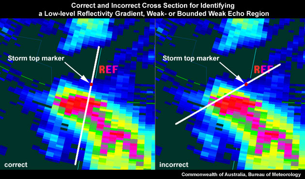
The image on the left is a correct cross section for identifying a tight low–level reflectivity gradient, as the most direct path from the low-level reflectivity core to the location of the upper level reflectivity core is used. The image on the right shows an inappropriate cross section, as the most direct path is not used.
- Is there a tight reflectivity gradient on the edge of the lower core in the vicinity of the reference point? If yes, a Tight Low-level Reflectivity Gradient is present.
Proper location of Tight Low-level Gradient on northern side in PPI.
Potential Difficulties in Detection
Radar Sampling – If the thunderstorm is too far away from the radar, the beam may overshoot the signature, and the broadening beam at a distance will also struggle to indicate the sharpness of the low-level reflectivity gradient.
Examples of Tight Low-level Refelctivity Gradients
Tight low-level reflectivity gradient on the northern flank of the storm. Note the reference point (storm top) is located right above the low level gradient.
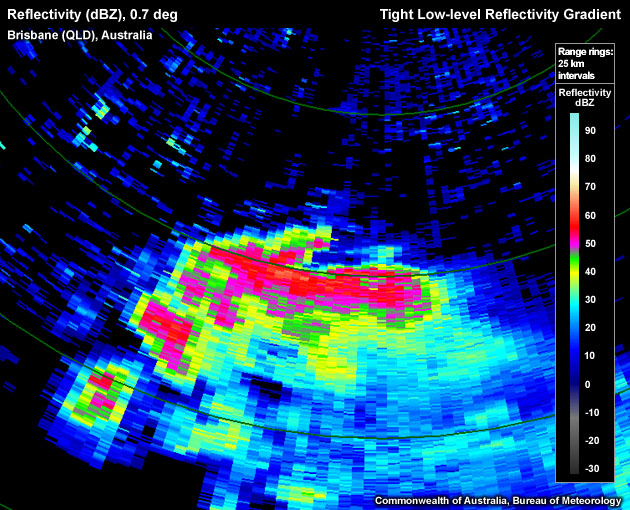
Tight low–level reflectivity gradient on northern flank of storm.
Very tight low-level reflectivity gradient on northern flank of the storm.
Very tight low-level reflectivity gradient on northern flank in PPI, left hand side in RHI.
Tight Low-level Reflectivity Gradient Look–a–likes
A segment of the edge of the low level core displays a tight low-level reflectivity gradient but is not located on the updraft/inflow side. The important characteristics required to confirm a Tight Low-level Reflectivity Gradient is that the gradient is located on the updraft/inflow quadrant of the thunderstorm and that the signature is persistent in time.
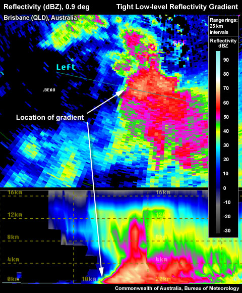
False Tight Low-level Gradient on left hand side in PPI. RHI shows no upper level core above tight gradient. Wrong location for a gradient that is to be used as a proxy for storm severity.
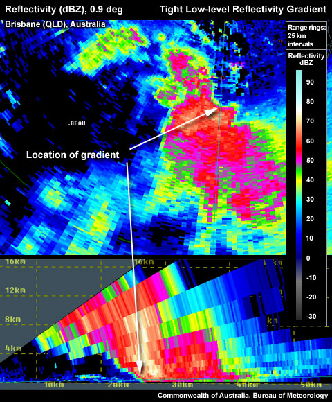
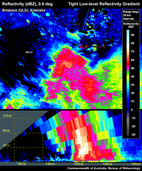
Proper location of Tight Low-level Gradient on northern side in PPI. RHI confirms with upper level core aloft.